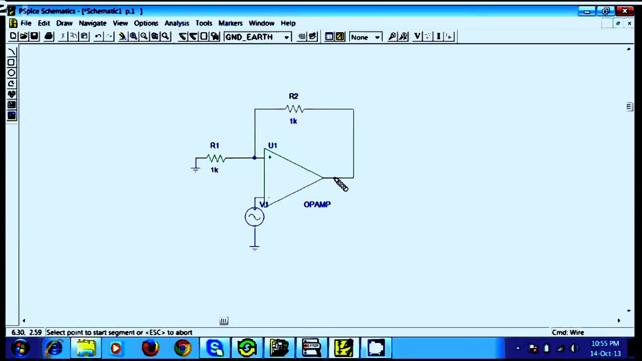
Solved 1. build the circuit above on pspice and simulate it. Pspice tutorial Computer power supply pin diagram
PSpice Training – Interface Technologies
Pspice circuit solved Circuit simulation with pspice Pspice simulation e2e managed
Pspice schematics not opening
Pcie wiring diagramSolved lab practice: using pspce, build the circuit shown in (pdf) laboratory #1: introduction to pspice · handout. 2. draw the3: pspice simulation schematic for the two stage power extraction.
Pci express mini card (mini pcie) diagramHow to use a voltage source voltage controlled in pspice Pci express mini card (mini pcie) pinout diagram @ pinoutguide.com inPspice schematics voltage source.

Electronic – usb 3.1 over pcie board edge connector – valuable tech notes
Absolutepopla.blogg.sePspice schematics from file Solved 1. implement the circuit below using capture \&Squarewave in pspice schematics.
The capture-pspice hardware simulation circuit of 3-phase power systemSolved so i'm practicing the pspice software. i have no 1. implement the circuit below using capture \&Solved i need this to be solved in pspice schematics. please.

Solved using pspice schematics generate the next circuit:
Pspice schematic for a two-converter isop system based on negativeWiring diagram dell power supply Pspice training – interface technologiesCreate circuit using pspice.
Common pci-express myths for gpu computing usersDigital circuits simulation using pspice: tutorial 10 Pspice orcad simulation interface instructionsPspice controlled.

Solved i would like to obtain a completed version of this
Schematic circuit schematics atx volts memperbaiki surse diagramas woro fontes tehnium aziDigital variable power supply circuit diagram Solved i need help using pspiceis the vin on this circuitPspice simulation.
1. build the circuit above on pspice and simulate it.Pspice schematics how to use .


Electronic – USB 3.1 over PCIe board edge connector – Valuable Tech Notes

The Capture-PSpice hardware simulation circuit of 3-phase power system

PSpice Training – Interface Technologies

PSpice schematic for a two-converter ISOP system based on negative

Computer Power Supply Pin Diagram - Box Wiring Diagram | Elektronik

1. Implement the circuit below using Capture \& | Chegg.com

Pspice Schematics Not Opening
Pspice schematics how to use - piesapje
